Undersizing or misaligning a screen with facility flow dynamics inevitably leads to catastrophic headloss, channel flooding, or premature equipment failure. Facility managers and design engineers often default to average daily flow (ADF) for sizing. This fails to account for peak wet weather flows, blinding factors, and the specific hydraulic limitations of different screen types. Specifying the correct mechanical screen requires a rigorous evaluation of minimum, average, and peak flow rates alongside channel hydraulics, approach velocities, and debris characterization. We see plants bypass raw sewage simply because a storm surge overwhelmed a screen sized only for average conditions. You must evaluate the hydraulic profile before looking at aperture sizes.
Peak Flow is the Baseline for Sizing: Mechanical screens must be sized to handle absolute peak hourly flow under maximum blinding conditions without exceeding headloss limits.
Velocity Dictates Maintenance: High approach velocities accelerate wear and force soft organics through the screen, while velocities that are too low cause grit and heavy solids to settle in the channel.
Aperture vs. Capacity Trade-Off: Smaller screen openings exponentially increase flow resistance and blinding rates, requiring larger screen surface areas or specific equipment designs to maintain throughput.
Hydraulic Integration is Non-Negotiable: The screen cannot be evaluated in isolation; channel dimensions, upstream conditions, and downstream water levels fundamentally alter screen performance.
You cannot select screening equipment without establishing precise flow parameters. Average Daily Flow (ADF) represents the total volume of wastewater flowing into a facility over 24 hours, divided by the number of days in the recording period. Maximum Month Flow (MMF) tracks the highest daily average flow over a 30-day span. Peak Hourly Flow (PHF) measures the absolute highest volume of water entering the plant during a single hour, typically during severe wet weather events or major industrial discharges.
Peaking factors fundamentally alter the structural requirements of the screen. A peaking factor is the ratio of peak flow to average flow. A facility with an ADF of 2 MGD and a PHF of 8 MGD has a peaking factor of 4.0. The screen must physically withstand four times the normal hydraulic force and debris load during a storm. If you ignore the peaking factor, the screen frame will buckle under the hydraulic pressure. Older collection systems with high inflow and infiltration (I&I) often see peaking factors of 5.0 or higher, demanding massive structural reinforcement for any installed equipment.
During flow surges, a specific sequence of hydraulic impacts occurs. Increased volume typically spikes the flow velocity through the screen before it significantly raises the water depth in the approach channel. This rapid velocity spike forces a massive amount of debris against the screen face in a matter of minutes. The open area vanishes. This leads to rapid, unexpected blinding before the automated cleaning mechanisms can react.
The initial velocity spike carries heavy, settled debris from the bottom of the collection system directly into the plant.
This debris impacts the screen face, rapidly reducing the available open area for water passage.
The upstream water level rises sharply as flow resistance increases across the blinded mesh.
Headloss exceeds the cleaning mechanism's maximum removal rate.
Water overtops the channel walls or triggers the emergency bypass weir.
Approach velocity determines how debris interacts with the screen face. The optimal approach velocity range strictly falls between 1.25 to 3.0 feet per second (0.4 to 0.9 meters per second). Maintaining this specific velocity window ensures debris reaches the screen without causing excessive structural strain or settling in the channel.
High-velocity flows carry severe consequences. When velocity exceeds 3.0 ft/sec, mechanical wear accelerates exponentially. High pressure forces pliable debris, such as rags, flushable wipes, and soft organics, directly through the mesh. Engineers call this extrusion. Extrusion defeats the purpose of the screen, passing the burden to downstream pumps and aeration basins. Furthermore, high velocity places immense structural stress on the screen frame, drive components, and anchor bolts.
We link high-velocity flows directly to increased lifecycle costs. Abrasive grit and heavy debris degrade wastewater screening equipment much faster when propelled at high speeds. Maintenance frequency spikes. Chains stretch, sprockets wear down, and rake teeth bend. Conversely, low-velocity flows present a different set of severe problems. When velocity drops below 1.25 ft/sec, grit deposition occurs in the approach channel. Heavy solids settle out of suspension before reaching the screen. This creates anaerobic conditions, generates hazardous hydrogen sulfide odors, and causes uneven flow distribution across the screen face.
Approach Velocity Impacts on Screen Performance | ||
Velocity Range (ft/sec) | Hydraulic Condition | Impact on Debris and Equipment |
|---|---|---|
Below 1.25 | Sub-optimal (Low) | Grit and heavy solids settle in the channel. Anaerobic conditions develop. Debris fails to reach the screen face evenly. |
1.25 to 3.0 | Optimal | Solids remain in suspension. Debris engages the screen face without extruding through the mesh. Normal equipment wear. |
3.0 to 4.5 | High | Soft organics and rags extrude through apertures. Accelerated wear on chains and sprockets. Increased headloss. |
Above 4.5 | Severe | High risk of structural deformation. Massive extrusion of solids. Potential for drive mechanism failure due to impact loading. |
Headloss is the drop in water level across the screen. It measures the energy lost as water pushes through the metal barrier and the accumulated debris. You calculate headloss by measuring the water depth immediately upstream of the screen and subtracting the water depth immediately downstream. High headloss indicates that the screen is restricting flow, which backs up water into the incoming sewer lines.
Flow resistance increases over time as the screen catches particulate. We refer to this accumulation as blinding. A clean screen presents minimal resistance. As rags, plastics, and organics cover the apertures, the open area shrinks. Water must force its way through a smaller space, causing the upstream water level to rise. If the cleaning mechanism fails to remove the debris fast enough, headloss reaches critical levels, triggering a bypass event.
Engineers must calculate headloss assuming a specific blinding percentage at peak flow. You never size a screen based on a 100% clean open area. For coarse screens, you typically calculate headloss assuming a 30% blinding factor. For fine screens, you must assume up to 50% or more blinding at peak flow. Failing to apply these blinding factors guarantees channel flooding during a storm surge. The calculation relies on the Bernoulli equation, factoring in the discharge coefficient of the specific mesh profile, the approach velocity, and the reduced open area.
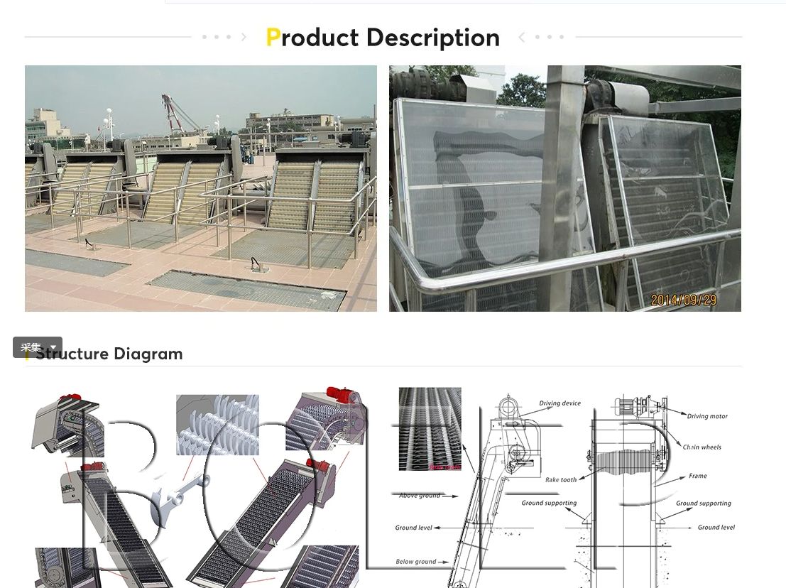
A bar screen for wastewater treatment stands as the optimal choice for high-volume, high-velocity influent carrying heavy, coarse debris. These screens utilize thick, vertical or inclined stainless steel bars. They intercept large objects like branches, bricks, and massive rag balls before they can damage sensitive downstream equipment. The teardrop or trapezoidal profile of modern bars helps prevent debris from wedging tightly between the gaps.
The robust nature of bar screens allows them to handle sudden flow surges without catastrophic deformation. When a storm pushes a massive surge of water and heavy debris down the channel, the thick steel bars resist the impact. The rake mechanisms physically tear through heavy debris mats, pulling them up and out of the flow path. However, this durability comes with a distinct limitation. Larger spacing between the bars means lower capture rates for fine solids. You pass the burden of fine filtration downstream to secondary screens or primary clarifiers.
Rotary drum screen wastewater applications handle flow rates differently by utilizing a significantly larger submerged surface area. The cylindrical design allows water to flow into the drum and out through the mesh, or vice versa. This geometry maximizes the available open area within a confined channel space, allowing a fine mesh to process a volume of water that would normally require a much wider channel if a flat screen were used.
The operational reality of drum screens requires careful hydraulic management. They are highly effective for fine screening, capturing particles down to 1mm or 2mm. However, they remain highly sensitive to sudden hydraulic surges. A rapid influx of water carrying high grease concentrations can rapidly blind the fine mesh. Once blinded, the drum acts as a dam. You must ensure upstream flow equalization or precise automated cleaning controls to prevent overflow. High-pressure spray bars must operate flawlessly to keep the mesh clear during peak events.
Step screens utilize movable and stationary lamellas to lift debris out of the flow. They excel at creating a "debris mat" on the screen face. This mat actually enhances capture efficiency, acting as an additional filtration layer that traps smaller particles. Step screens manage moderate flow variations well, as the lifting motion continuously clears the lower section of the screen to allow water passage. They do not require a separate rake mechanism, which simplifies maintenance.
Perforated plate screens offer exceptionally high capture efficiency. They utilize panels with precisely punched holes to block hair, seeds, and small plastics. However, we emphasize their strict flow rate limitations. Perforated plates experience rapid headloss accumulation if undersized. Because they capture so much material, they blind incredibly fast. You must size them generously and ensure the cleaning brushes or water jets operate continuously during peak flows. If the flow velocity exceeds the design parameters, the water pressure will simply force soft debris through the perforations.
An inverse relationship dictates screen performance: as mesh or aperture size decreases, the open area decreases, exponentially increasing flow resistance. You cannot install a fine screen in a channel designed for a coarse screen without drastically altering the hydraulics. The smaller the holes, the harder the water must work to push through. This increases the velocity through the remaining open area, which in turn increases the headloss.
A coarser mesh allows for a much higher flow rate. It requires less frequent cleaning cycles because small debris passes right through. This keeps headloss low and prevents channel flooding. However, you sacrifice downstream equipment protection. Pumps will clog. Aeration basins will accumulate rags. You must balance the need for hydraulic throughput with the absolute necessity of protecting your biological processes. You achieve this balance by running a primary coarse screen followed immediately by a secondary fine screen.
Flow rate directly dictates the required speed and frequency of the automated cleaning mechanism. Whether your screen uses rakes, brushes, or high-pressure spray bars, the cleaning system must outpace the blinding rate. During average flows, the screen might run a cleaning cycle once every hour based on a timer. During peak flows, it must run continuously, triggered by an ultrasonic level sensor detecting high differential headloss.
Undersizing the cleaning mechanism relative to the flow rate creates severe operational risks. If the rake travels too slowly, debris accumulates faster than it is removed. This results in permanent blinding. The water level overtops the screen. You experience a bypass event, sending raw, unscreened sewage directly into your treatment plant. The mechanical drive must possess the torque and speed to handle worst-case debris loading without stalling.
You must establish a strict framework for calculating the required screen area. Never size based on average daily flow. Calculate the required surface area based on peak hourly flow. Apply the maximum anticipated blinding factor for your specific debris type. Factor in the specific open area percentage of the chosen wastewater pretreatment screen.
Determine the absolute Peak Hourly Flow (PHF) from historical plant data.
Select the target aperture size based on downstream equipment tolerances.
Identify the clean open area percentage of the specific screen model.
Apply a 30% to 50% blinding factor to reduce the effective open area.
Calculate the resulting headloss at PHF using the reduced open area.
If the calculated headloss at peak flow exceeds your channel's freeboard, you must increase the screen size. You can achieve this by widening the channel, deepening the channel, or selecting a screen design that offers more submerged surface area, such as an inclined screen or a drum screen. Sizing for the worst-case scenario prevents catastrophic failures during severe weather.
Channel width and depth directly influence the approach velocity and the submerged area of the screen. A narrow, deep channel creates higher velocities. A wide, shallow channel reduces velocity but may not provide enough submerged depth to utilize the screen's full capacity. You must match the channel dimensions to the specific hydraulic profile of the screen. Modifying existing concrete channels is expensive, so selecting equipment that fits the existing hydraulic profile is often necessary.
Straight approach channels are an absolute necessity. You must design the channel to prevent eddy currents, uneven loading, and localized high-velocity zones. If the channel bends immediately before the screen, water will slam into one side of the equipment. This causes uneven wear, localized blinding, and structural twisting of the frame. Ensure a straight approach of at least ten times the channel width whenever possible. If a bend is unavoidable, install flow-straightening baffles upstream of the screen.
Engineers frequently overlook the problem of minimum flow rates during night cycles or dry weather. While peak flows threaten to flood the channel, minimum flows threaten to choke it. When the water volume drops significantly, the velocity plummets. This creates a settling basin right in front of your pretreatment equipment.
If the incoming flow has a high concentration of large, heavy debris, a higher minimum flow velocity is strictly required just to push the debris to and through the screen face. If velocity drops below 1.25 ft/sec, bricks, gravel, and heavy sludge settle in the channel invert. To mitigate this, facilities often use channel aeration or strategically placed water jets to keep heavy solids in suspension during low-flow periods. Alternatively, you can design a narrower low-flow channel parallel to the main channel.
You cannot rely on a single mechanical screen to handle every possible scenario. Equipment requires maintenance. Power failures occur. Extreme 100-year storm events exceed design capacities. Designing bypass channels is a strict necessity for facility protection. A plant without a bypass channel is a plant waiting to flood.
Install a bypass channel equipped with a manual bar screen parallel to the main mechanical screen. Use an overflow weir set at a specific elevation. If the mechanical screen blinds and headloss reaches a critical level, the water naturally overtops the weir and flows through the manual screen. This protects the plant from flooding while still providing a baseline level of coarse filtration during emergencies. Ensure the manual screen has an aperture size large enough to handle the diverted peak flow without instantly blinding itself.
Do not accept off-the-shelf sizing charts for critical infrastructure. Advise your procurement team to look for a mechanical screen manufacturer that provides verifiable hydraulic calculations. They should offer computational fluid dynamics (CFD) modeling for complex channel layouts. This proves they understand how their equipment interacts with real-world fluid dynamics. Generic sizing charts fail to account for site-specific variables like upstream bends or unusual debris compositions.
Demand complete transparency regarding the assumptions used in their headloss and blinding calculations. If a manufacturer claims a remarkably low headloss, ask for the blinding percentage they used in the formula. If they assumed only 10% blinding at peak flow, reject the proposal. The calculations must reflect the harsh reality of your specific wastewater composition. Ask to see the raw math, including the discharge coefficients they apply to their specific mesh profiles.
Evaluate construction materials strictly in the context of high-velocity, abrasive flows. Standard 304 stainless steel may suffice for benign municipal wastewater. However, if your flow contains high levels of chlorides, industrial runoff, or abrasive grit, you must upgrade to 316 stainless steel or duplex stainless alloys. The material must resist both corrosion and physical abrasion. Grit moving at 3.0 ft/sec acts like sandpaper on submerged metal components.
Robust drive mechanisms and overload protection systems are critical. When a massive surge pushes a heavy log or a dense rag ball into the screen, the drive motor experiences extreme torque. The equipment must feature mechanical shear pins or electronic torque limiters. These systems immediately shut down the motor if it jams, preventing the frame from twisting or the drive shaft from snapping under the strain of peak flow debris loading. Inspect the thickness of the side frames and the diameter of the drive shafts before approving any submittal.
Audit historical flow data to establish absolute peak hourly flow and maximum blinding conditions for your specific site.
Measure existing channel dimensions to calculate approach velocities during both low-flow night cycles and high-flow storm events.
Require computational fluid dynamics (CFD) modeling from vendors to verify headloss calculations before finalizing equipment selection.
Design a parallel bypass channel equipped with a manual bar screen to handle extreme storm surges and maintenance downtime.
Install electronic torque limiters on all drive motors to prevent structural damage during sudden heavy debris loading.
A: The standard maximum approach velocity is typically 3.0 ft/sec (0.9 m/s). Exceeding this limit causes excessive mechanical wear and forces pliable debris, like rags and soft organics, directly through the screen openings. Specific limits depend on the screen type and manufacturer specifications.
A: Screens must be sized for the absolute peak flow, which is often 2 to 4 times the average daily flow. During a surge, velocity spikes before channel depth increases, causing rapid debris loading. Sizing for peak flow prevents channel flooding and equipment bypass during storm events.
A: Flow resistance increases due to the blinding effect. As accumulated particulate, rags, and plastics cover the screen's apertures, the open area shrinks. This restricts water passage, raises the upstream water level (headloss), and necessitates automated cleaning cycles to restore flow capacity.
A: Yes, they handle large volumes efficiently due to their high submerged surface area. However, they are highly sensitive to sudden hydraulic surges and heavy grease loads, which can blind the fine mesh instantly. They require careful upstream flow equalization to operate reliably during peaks.
A: If velocity drops below 1.25 ft/sec, grit and heavy solids settle out of suspension before reaching the screen. This leads to severe channel blockages, anaerobic conditions, odor generation, and an inability to push heavy debris against the screen face for removal.
A: Engineers calculate headloss using variations of Bernoulli’s equation. The calculation factors in the approach velocity, total flow rate, the specific open area of the clean screen, and an assumed blinding percentage (typically 30% to 50%) to simulate worst-case flow resistance.